 |
Figure 1: a possible layout plan for a typical small recording studio
|
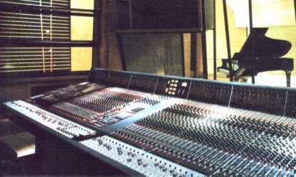 |
Figure 2: a little over half of a large commercial console (mixing desk) at (and photo courtesy of) Metropolis Studios, London. The studio room on the other side of the glass is shown in the article heading photo. The author did not, sadly, design Metropolis Studios...
|
 |
Figure 3: here we show the basics of true (Blumlein) stereo recording, and its extension to three dimensions as Ambisonics
|
 |
Figure 4: all that we can do on a typical mixing desk is use the pan-pot to set volumes and give a false impression of panoramic position using the Haas effect. Here is part of a typical (measured) quality pan-pot characteristic
|
 |
Figure 5: a floating floor, supported on the existing floor but (we hope) isolated from it. Usually our hopes are confounded...
|
 |
Figure 6: an isolated and floating floor. Here a complete new floor is built, with the original left in place. Then, a floating floor is put on top of the new supports. This works, usually...
|
 |
Figure 7: a graph of Sound Reduction Index (SRI) as a function of surface mass. More massive equals more sound loss (and cost!)
|
 |
Figure 8: standard Noise Rating curves. These allow a shorthand way of stating how much noise reduction is needed - you can just specify 'to NR 10' and that says it all. In theory!
|
 |
Figure 9: the Noise Spectrum of average and quiet homes, drawn to the same scale as Figure 8. If you compare this with the NR curves above in Figure 8, then you'll see that you just might be lucky enough to get away without too much work...
|
 |
Figure 10: one way of building a studio window. The third pane of glass adds little in practice, but it doesn't add that much to the (already high) cost, so why not...?
|
 |
Figure 11: how to use isolating audio transformers to keep the hum and noise level down and the musicians (and desk engineer) alive. Assuming, of course that that is regarded as important...[that is a JOKE, right? ...I think %-]
|